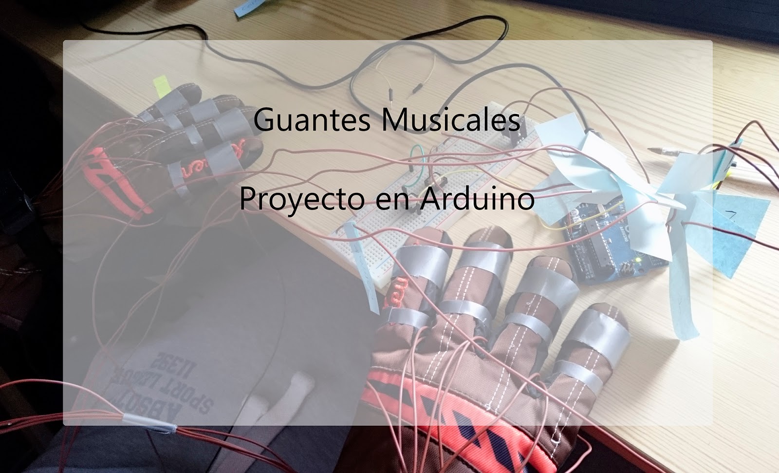
Arduino – Maching Learning
Authors: Jaime Rueda Carpintero, Cristian Fernando Calva Troya, Luis Ovejero Martín and Valery Isabel Cortez Fernández.
1. Introduction
The project consists in a clasificator of tools, able to classify 4 types of tools: nut, bolt, butterfly and washer. The classification of the different types of the tools will be carried out by an artificial intelligence created by us. The system consists of a belt wich is the tasked to carry the tool to the camera of the plate and to the classificator arm, wich in function of the type of tool, it is going to move in the direction of the correct box. The arm will always make the same movement, but the boxes will be the ones that will vary their position depending on the classified type.
2. Used material
- Arduino Uno: principal plate tasked to move the belt, comunicate with the Arduino Nano 33, move the arm and move the boxes.
- Servomotor: tasked to move the arm. One servomotor is tasked to move the base and the another one is tasked to rotate the box of the arm
- Joystick: depending of the movement to left, right, up or down is going to classify the tool by a nut, bolt, butterfly or washer.
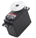
- Servomotor Hitec HS-433: servomotor with a bigger power than the servomotors of the arm. Tasked to move the belt.
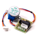
- Stepper motor: move the platter of the boxes of the tools classified.
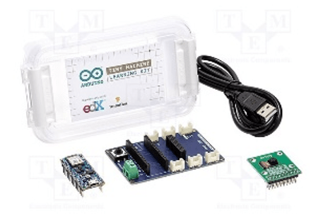
- Maching Learning Kit: consist of the plate Arduino Nano 33 and the camera OV7675. The camera will capture an image of the tool to classify and will send the image to the plate, wich will be able to classify and send the information due to the modelo of inteligence artificial trained.
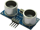
Note*: Although we have used the ultrasonic sensor and the electromagnet in our prototypes, finally we have not included them in the final version due to problems that will be specified later.
3. Project assembly in Tinkercad
For the circuit development in the tinkercad plataform, we see some little limitations. These limitations are going to make the circuit mildly different from the one we finally made in the project.
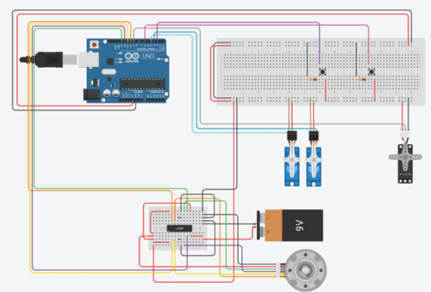
First of all, there is not the controller plate of the stepper motor so we had to create a small circuit to replace it. The other change is that we could not add the joystick in the circuit of the platform due to it does not exists.
4. Inteligence Artificial
For the IA development of our proyect, we tried to implement by two different forms: from the library of TensorFlow, coding all the IA, and from the web platform of EdgeImpulse. The implementation of the IA has been very difficult due to the foul of documentation, problems with versions, problems with the memory of the plate…
The first model of IA that we created was created by the library of TensorFlow. Python is used and before the development of our model we had to develop a dataset (set of data that the model will take to train and recognize patterns of the data). The dataset was done through the page of EdgeImpulse with the camera of the Arduino Nano 33.

The dataset consist of near 1200 photos, that is going to split between training photos and testing photos. The training photos will be used by the model to recognize patterns of the type of classes that we had specified in the images. Once the model is trained, we are going to pass images that we know the class of the image and the model will predict the class.
Once the dataset is finished, is the hour to code our model in Python. Here is an example of image classification that we have found very useful:
https://www.tensorflow.org/tutorials/images/classification?hl=es-419
The first problem we found was when downloading all the TensorFlow libraries. The library that gave us the most problems was Keras. In more recent versions of Python it gave problems when installing the library. The version that worked best for us was Python 3.7.
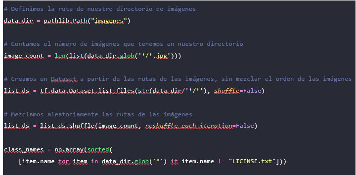
This is the configuration of the directories where is the dataset with the images. The name of the classes will be taken in function of the name of the folders. The dataset is organized like this:

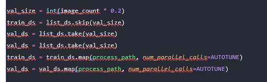
We have defined the dataset that we are going to use for training and validation. The optimum is to have 20% validation and 80% training. The train_ds will take the last images of its corresponding percentage and the val_ds the first of 20%. We map the variables to have an image-label pair. Once we have divided the images into batches, giving them a size and various operations, we now move on to training the model.
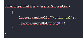
This variable is one more layer in our neural network that will be tasked to transform the input images. This particular function rotates the images to have more variety.
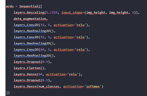
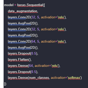
We had a lot of different neural networks, but this is the most efficient neural network we could make. The first thing we do in our neural network is to rescale the training photos to 64 x 64 to make the model lighter and to grayscale it. We apply the data processing function that I have mentioned before and we already begin to apply the neurons:
- Conv2D: convolution layer. Applies various operations on the input images for greater efficiency.
- MaxPooling2D: reduces the resolution of the output of convolutional layers.
- Dropout: layer that prevents overfitting.
- Flatten: transforms the image from the previous output into an array.
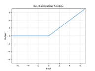
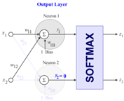
- Dense: obtains the probability of each class through its softmax activation function from the obtained array.
Once we have trained the model with a total of 100 epochs and a learning ratio α of 0.01, we save the model in our directory with an extension of .h.
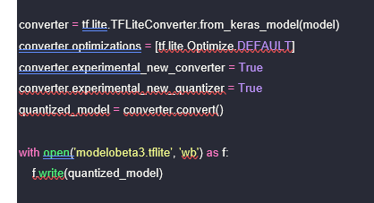
Another of the problems that we found is that the model.h is not capable of being supported by the Arduino Nano 33 due to the low capacity of the plate, so we will have to transform the model to a TensorFlow Lite model and then to a model of TensorFlow Lite Micro.
For the first transformation to micro, we created the following method where the TensorFlow Lite converter is used and we are going to save the model with the name that appears below:
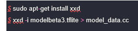
Once transformed, we will now transform the model into a C file containing a one-dimensional array of the model using two commands in Linux:
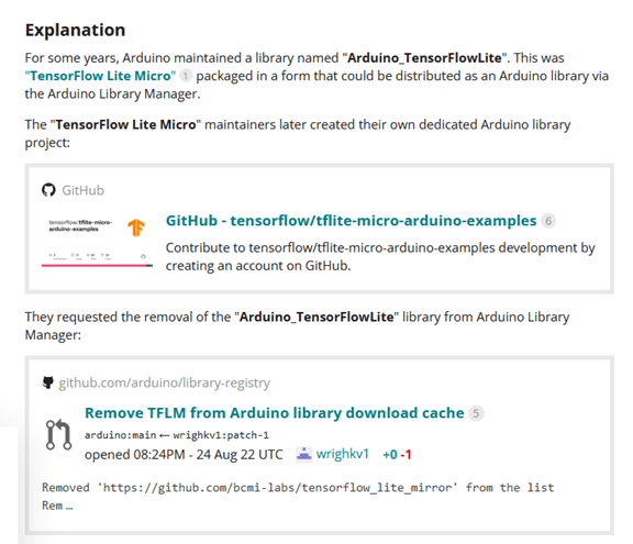
Once we have already created the model, we go to the Arduino IDE. One of the new problems that we have encountered has been the fact of not being able to find the TensorFlow Lite Micro libraries for Arduino. The libraries until recently were located here: https://www.tensorflow.org/resources/libraries-extensions?hl=es-419. After digging we found out that the creators of these libraries had problems with the Arduino creators and had to delete the libraries. Currently, the libraries can be obtained on GitHub from some users who had these libraries, as is the case with this repository:
https://github.com/mbernico/tflite-micr
The library is imported like any other in the IDE and now we move on to configuring the camera and the model. So that the board does not have memory problems, we have to prepare the model. First, we have to specify what operations have been carried out in the neural network:
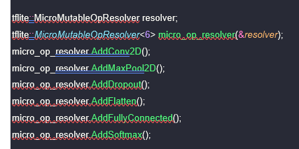
However, due to issues between versions of Keras and TensorFlow, the AddConv2d, AddMaxPool2D and layers.Rescaling cannot be compiled. Therefore, we had to create a new neural network with layers that are in the appropriate version, such as Conv2D and AvgPool2D, in addition to removing the Rescaling. This model has lost efficiency and is less reliable than the previous one but is supported by an older version:
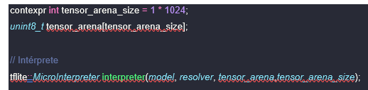
Now we will go on to predefine the memory area that we are going to use for the input, output or other TensorFlow arrays (it must be adjusted by eye):
Once the above is done and the camera is configured, we run the file and it fails again. The error that happens to us now when executing is that one of the versions which we compiled the model to TensorFlow Lite Micro is not compatible with the version that we have downloaded from GitHub. We couldn’t fix this bug as we couldn’t find a library that was compatible with our model.
In the following link there is a discussion thread from the Arduino forum where what happened is explained. Also, there are links to older TensorFlowLite libraries.
Although our team could not complete this phase due to lack of time, we invite future groups to try it, starting from the point where we left off.
Finally, to avoid problems with the library we have made use of the EdgeImpulse web platform, which is a page where we will be able to create a dataset, train a model, edit the model, export the model and various other functions. We have only had to specify to the page what our dataset would be like, what we want to classify and the neural network. The neural network that we have used in EdgeImpulse is very similar to the network of the previous model in that it generates a very lightweight and efficient model. Here is a configuration of the input images similar to the previous model:

Training of the model:
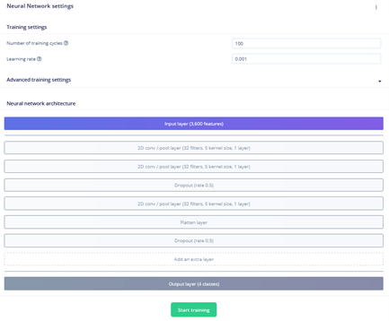
Here we are shown a graph of the success rate that the model has had in the learning stage and the loss:
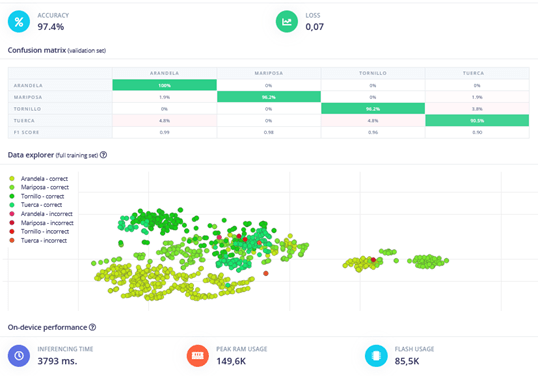
We can also observe how the data has been dispersed when classifying them. The model size is 149K, where the maximum size of the board is 256K. We have noticed how if the model weighs more than 160K, the board runs out of memory and the model cannot be inserted.
The model that we have could be retrain(may be the case that when adjusting the weights of the neural network improves or worses the model) and tested with the data of the dataset that can predict the class to wich it belongs. After all, the testing part would be done by us in our embedded system when identifying one object or another.
Finally, the model already implemented in the Arduino IDE has not given any problem and is able to take photos. The problem appear when we try to set a connection between the Arduino Uno and the Arduino Nano 33. The connection has been done through the communication protocol I2C, where we will be able to communicate the two plates through the Serial. We were able to send a serial from the Uno to the Nano and the Nano recibes it. However, when the Nano wars the Uno and sends a signal it gave problems and couldn’t send correctly. The plate of the Arduino Nano 33 has a very limited number of pins, so we couldn’t find a better solution to establishing a communication.
All the code that we explained previously it’s find in the next link of GitHub:
https://github.com/jaimachu/Maching-Learning-TensorFlow
5. Hardware
In this section, we are going to talk about the materials used for the development of the physical part of the project, the cost of these materials, the assembly process, the problems that arose during it, and the solutions that were implemented.
Material
In addition to the components we have seen earlier, for the construction of the structure where all the parts of the project will be placed, we have used plywood as it is easy to handle. We have also used this material to create the different pieces of the robotic arm, and for its basket, we have used a cut-out cardboard cup. Screws and double-sided tape were used to assemble these pieces.
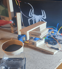
For the conveyor belt structure, we can see that we have used wooden sticks that were cut to create the belt path. We have also created pivoting axes for the belt to move forward, and cardboard boxes where tools can be placed so that the camera does not have trouble recognizing the objects and to prevent them from falling off the belt.
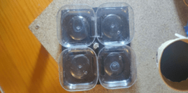
Lastly, for the tool sorting box, we have used small plastic bottles that were cut and a piece of foam board.
| Material costs | |
| Wooden sticks | 6.55€ |
| Particle board | 0.75€ |
| Screws | 1.20€ |
| Cardboard | 0.50€ |
| Double-sided tape | 1.15€ |
| Plywood boards | 12.98€ |
| Electromagnet | 5.00€ |
| 180º Servomotors | 12.00€ |
| Continuous rotation servomotor | 12.50€ |
| Total: 52.63€ |
Implementation, failures and solutions.
For the implementation of the project, we divided it into different parts: the conveyor belt, the mechanical arm, and the sorting boxes.
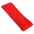
For the conveyor belt part, we used the continuous rotation servomotor, wooden sticks to create the path for the belt, small sticks as pivoting axes for the belt, and an exercise band as the belt itself.
The servo will start moving when we press the button indicating that the belt should move forward. Then, we will use another button to signal the Arduino Nano 33 to process the image of the object. The joystick will be used in this part to indicate the object identified by the AI.
Firstly, to create the conveyor belt, we initially considered using the ultrasonic sensor from the kit to determine when the box with the object reached the processing location. However, this resulted in numerous failures, so we decided to replace the sensor with a button to move the belt to the exact position. We also attempted to use the stepper motor from the kit to drive the belt, but it was too slow, prompting us to purchase a different servomotor.
For the mechanical arm, we crafted the pieces using plywood and assembled them with double-sided tape and screws. The initial design involved an electromagnet instead of a basket. However, the purchased magnet lacked sufficient strength to lift larger screws, leading us to change the design and replace the magnet with a basket.
The final part involved the sorting boxes. We utilized the kit’s stepper motor to rotate the boxes based on the recognized tool. After pressing the button to signal the AI to start identifying, the motor would rotate to position the boxes correctly. The arm would then pick up the tool and place it in the appropriate box. Afterwards, the boxes would return to their default position.
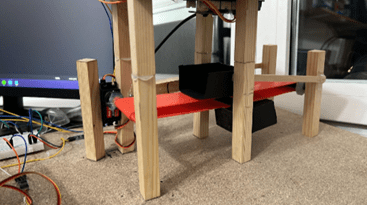
In this part, there weren’t many issues, aside from adjusting the motor speed. However, we realized that it wasn’t crucial, so we kept it at its default setting. Finally, we assembled all these components on a particle board, to which we attached legs to elevate it from the table. This was done to create a hole to accommodate the stepper motor, allowing the sorting boxes to sit lower. This ensured that there would be no collisions when rotating the arm’s basket to release the object.
6. Software
In this part we will explain how the software works and its use cases.
Cases of use
First of all, press the yellow button to move the tape to its position. Once in the corresponding place, press the red button to indicate that the object can be identified. Once the object has been identified, we have four use cases:
- Screw: The first case is that a screw has been identified. For this case we will not move the boxes, we will only move the arm to pick up the tool and to drop it in the default position box, as this will be the one that stores the screws.
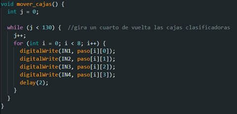
- Nut: In this second case, when the object is identified as a nut, we will move the boxes only a quarter of a turn to store it in the next box, the arm will move and finally the boxes will turn three quarters of a turn to put them in the same position in which they were at the beginning.
- Washer: In the third case, after recognising the washer, we move the boxes, half a turn to position the third box at the point where the arm releases the tool, the arm moves and we turn again half a turn.
- Butterfly: In this last case we turn the boxes three quarters of a turn, move the arm and turn the boxes again only a quarter turn to leave them as they were at the beginning.
Now that we know how the different use cases work, let’s look at the code.
Code
As we are going to explain the code in depth in the project video, here we are going to see some of the most important parts.
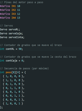
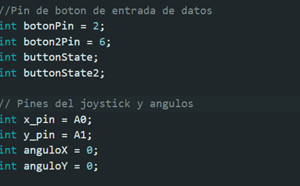
The first thing we can see is the declaration of some constants that we will use to indicate the stepper motor pins, the declaration of the servo motors we are going to use, counters to measure the degrees of the 180 degrees servo position, an array to store the stepper motor positions and the input pins for the buttons together with the assignment of the joystick pins and the degrees to use the joystick.
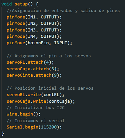
After this we move on to the setup part. This part is executed only once, so here we are going to assign which type of pins are going to be the input or output pins. We are also going to assign the corresponding pin to each servo, say what is the initial position of the 180’s and start the serial and I2C bus.
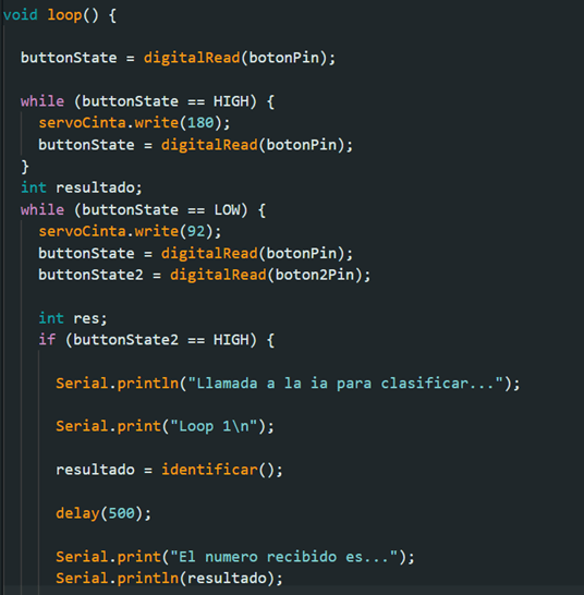
After the setup we move on to the loop. The loop will be executed in a loop after the setup. Here we are going to check the state of the yellow button, if it is pressed or not. If it is pressed, we are going to make the tape move forward and if it is not pressed, we are going to stop it.
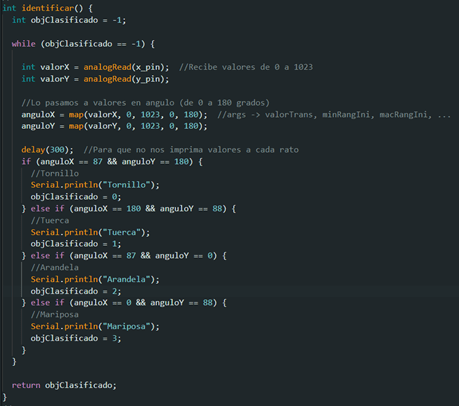
If the tape is stopped and the yellow button is not pressed, we will check the status of the red button. If the yellow button is not pressed and we press the red button, the part of the code that calls the Arduino nano 33 board to identify the object will be executed. Finally, as we could not make the two boards communicate bidirectionally, this part will call the identify function. This function will read the data entered thanks to the joystick and depending on the position of the joystick it will send one number or another, this number will correspond to the recognized object.
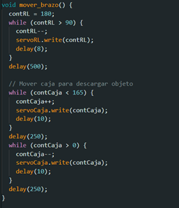
After receiving the output number of the identify function we will move the arm to the tape to pick up the object. Once it is placed, the tape will move to drop the object into the basket on the arm and will move back so as not to interfere with the movement of the arm.
Finally, we will call the organize method so that the sorting boxes are placed in the correct way and the arm can drop the object. After this we would go back to the beginning so that we can read the state of the button again and continue moving the tape.
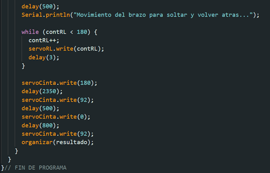
Some of the most important methods in the program are identify() which reads the state of the joystick to return the number corresponding to the sorted object, or move_arm() and move_boxes() which move the servomotors of the arm and move the stepper motor to place the boxes, respectively.
In the following GitHub link, you can find all the code of the project:
https://github.com/jaimachu/Maching-Learning-TensorFlow
Video demostration:
https://drive.google.com/file/d/1MumZYnQjMaIz4Ud0cV5qCC66U85KyDwa/view?usp=share_link